Recently, I’ve been looking at building ‘esk8-nrf24-remote’. Which can be found at :
Thingiverse (LINK), Source Code + Wiki (LINK).
This Remote Controller has very ergonomic Design, similar to ‘boosted-boards’ remote. With a difference that this one can display Real Time Speed/Battery Level and many more by receiving Ack-payload from the Receiver, which beforehand gets the data from VESC Open Source Electric Speed Controller. Nice feature, but I have to make it, right?
When viewed from the Maker’s view, the remote requires a lot of short wires to be routed. Mainly for Power(2), OLED(4), Hall-sensor(3), nRF24l01(7), Switch(2). At least 16 wires need to be soldered on each side, so it is clearly a Pain-In-The-Ass process ahead. But luckily, nowadays, making a custom PCB and ordering them costs only few-bucks, and it is much neater, removing un-necessarily thick wires, and can be produced in bulk, so if I want to build a lot of Remote, PCB is definitely a way to go. But I didn’t know how to make PCB.
Actually, I have built one about one year ago, I don’t remember what that was, but it was some-kind of ATiny series adapter or some sort. But I used ‘Altium-Circuit-Designer’ back then, and was pretty much overwhelmed by too many options & Bulky program. So this time, I tried ‘EasyEDA’. Which allows me to make PCB on the Web. No lagging, very convenient!
Link to the Very Nice Tutorial I followed: PART1, PART2, PART3
After investing about 3 hours into this, my first(second, maybe) PCB was complete!
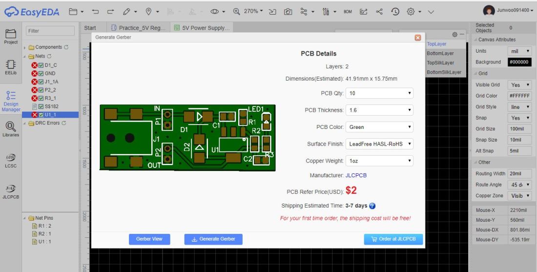
And what a Ridiculous Price! ‘JLC-PCB’ is definitely a killer in PCB manufacturing. I have no Idea how they can manufacture small-amount, custom-pcb so Cheaply 🙂
Making a PCB was pretty Straight-forward process, just like 3D modeling. And since software(EasyEDA) itself was very easy to use, everything worked flawlessly.
After this Post, I will start designing the Custom-PCB for Remote Controller!
